Alternating Current – Physics Class 12 Notes
Chapter – 7
Alternating Current
1. Alternating Current and RMS Values
An alternating voltage varies sinusoidally with time: v = vm sin ωt, where vm is the peak value and ω = 2πf. The average of a sinusoidal current over a complete cycle is zero, so we use the root mean square (rms) or effective value: the steady current that produces the same heating in a resistor.
Irms = Im/√2 = 0.707 Im; Vrms = Vm/√2. AC meters read rms values; “220 V mains” means Vrms = 220 V.
Numerical 1: The rms voltage of the domestic supply is 220 V. Find its peak value.
Given: Vrms = 220 V
Formula: Vm = √2 Vrms
Solution: Vm = 1.414 × 220
Answer: Vm ≈ 311 V
2. AC through R, L and C

Circuit | Current for v = vm sin ωt | Opposition | Phase | Average power |
|---|---|---|---|---|
Resistor R | i = (vm/R) sin ωt | R (independent of f) | i in phase with v | VrmsIrms |
Inductor L | i = (vm/XL) sin(ωt − π/2) | Inductive reactance XL = ωL | i lags v by 90° | zero |
Capacitor C | i = (vm/XC) sin(ωt + π/2) | Capacitive reactance XC = 1/ωC | i leads v by 90° | zero |
Derivation: Current in a pure inductor
- Applying Kirchhoff’s loop rule: vm sin ωt − L di/dt = 0, so di/dt = (vm/L) sin ωt.
- Integrating: i = −(vm/ωL) cos ωt = (vm/ωL) sin(ωt − π/2).
Result: im = vm/XL with XL = ωL; current lags voltage by π/2. XL increases with frequency (an inductor blocks high-frequency AC and passes DC).
Derivation: Current in a capacitor
- q = Cv = Cvm sin ωt.
- i = dq/dt = ωCvm cos ωt = (vm/XC) sin(ωt + π/2).
Result: XC = 1/ωC; current leads voltage by π/2. A capacitor blocks DC (XC → ∞ as ω → 0) and passes high-frequency AC.
Numerical 2: Find the reactance of a 0.5 H inductor at 50 Hz and the rms current when it is connected to a 220 V, 50 Hz supply.
Given: L = 0.5 H, f = 50 Hz, Vrms = 220 V
Formula: XL = 2πfL; Irms = Vrms/XL
Solution: XL = 2 × 3.1416 × 50 × 0.5 = 157.1 Ω; I = 220/157.1
Answer: XL ≈ 157 Ω; Irms ≈ 1.40 A
Numerical 3: Find the reactance of a 10 μF capacitor at 50 Hz and the rms current on a 220 V, 50 Hz supply.
Given: C = 10 × 10-6 F, f = 50 Hz
Formula: XC = 1/(2πfC); I = V/XC
Solution: XC = 1/(2 × 3.1416 × 50 × 10-5) = 318.3 Ω; I = 220/318.3
Answer: XC ≈ 318 Ω; Irms ≈ 0.69 A
Numerical 4: A voltage v = 311 sin 314t (in volts) is applied across a 100 Ω resistor. Find the rms current and the average power.
Given: vm = 311 V, R = 100 Ω
Formula: Vrms = vm/√2; Irms = Vrms/R; P = Vrms2/R
Solution: Vrms = 311/1.414 ≈ 220 V; Irms = 220/100; P = 2202/100
Answer: Irms ≈ 2.2 A; P ≈ 484 W
3. Series LCR Circuit
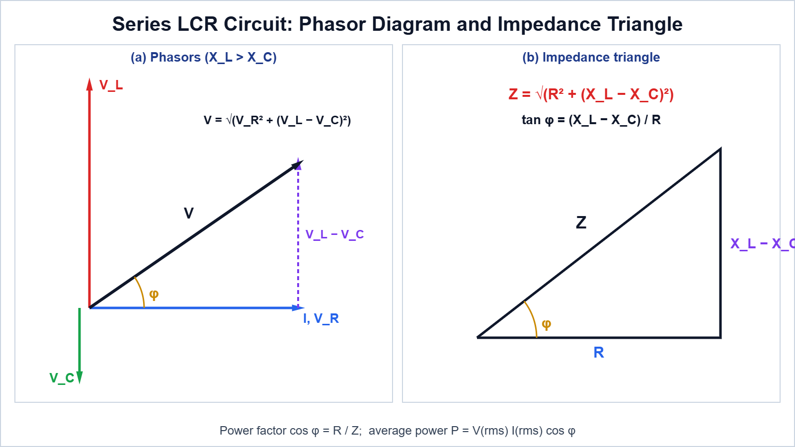
Derivation: Impedance of a series LCR circuit (phasor method)
- The same current i = im sin(ωt + φ) flows through R, L and C. Take the current phasor as reference.
- VR = imR is in phase with I; VL = imXL leads I by 90°; VC = imXC lags I by 90°.
- VL and VC are opposite, so their resultant is (VL − VC), perpendicular to VR.
- vm2 = VR2 + (VL − VC)2 = im2[R2 + (XL − XC)2].
Result: Z = √[R2 + (XL − XC)2], im = vm/Z, and tan φ = (XC − XL)/R for i = im sin(ωt + φ). If XL > XC the circuit is inductive (current lags); if XC > XL it is capacitive (current leads).
4. Resonance

When XL = XC, the impedance is minimum (Z = R) and the current is maximum. This happens at the resonant frequency ω0 = 1/√(LC), i.e. f0 = 1/(2π√(LC)). Resonance is possible only if both L and C are present. The quality factor Q = ω0L/R = 1/(ω0CR) measures the sharpness of resonance: smaller R gives a sharper peak. Use: tuning of radio and TV receivers.
Numerical 5: A series LCR circuit has L = 0.1 H, C = 10 μF and R = 10 Ω. Find the resonant angular frequency, the resonant frequency and the Q-factor.
Given: L = 0.1 H, C = 10-5 F, R = 10 Ω
Formula: ω0 = 1/√(LC); f0 = ω0/2π; Q = ω0L/R
Solution: LC = 10-6, so ω0 = 1000 rad s-1; f0 = 1000/6.2832; Q = 1000 × 0.1/10
Answer: ω0 = 1000 rad s-1; f0 ≈ 159 Hz; Q = 10
5. Power in an AC Circuit; Power Factor
Derivation: Average power
- v = vm sin ωt and i = im sin(ωt + φ).
- Instantaneous power p = vi = vmim sin ωt sin(ωt + φ) = (vmim/2)[cos φ − cos(2ωt + φ)].
- The average of cos(2ωt + φ) over a cycle is zero.
Result: P = VrmsIrms cos φ = Irms2R. Power factor cos φ = R/Z.
Case | φ | cos φ | Power |
|---|---|---|---|
Pure resistor | 0 | 1 | maximum |
Pure L or pure C | 90° | 0 | zero (wattless current) |
LCR at resonance | 0 | 1 | maximum (Vrms2/R) |
Remember: A low power factor means a large current for the same useful power, so larger losses in transmission lines; capacitors are used to improve the power factor of industrial loads.
Numerical 6: A series circuit has R = 30 Ω, XL = 80 Ω and XC = 40 Ω, connected to 200 V rms. Find Z, Irms, the power factor, the phase angle and the average power.
Given: R = 30 Ω, XL = 80 Ω, XC = 40 Ω, V = 200 V
Formula: Z = √[R2 + (XL − XC)2]; cos φ = R/Z; P = VI cos φ
Solution: Z = √(900 + 1600) = 50 Ω; I = 200/50 = 4 A; cos φ = 30/50 = 0.6; tan φ = 40/30, φ ≈ 53.1°; P = 200 × 4 × 0.6
Answer: Z = 50 Ω; I = 4 A; cos φ = 0.6; current lags by 53.1°; P = 480 W (check: I2R = 16 × 30 = 480 W)
6. Transformer
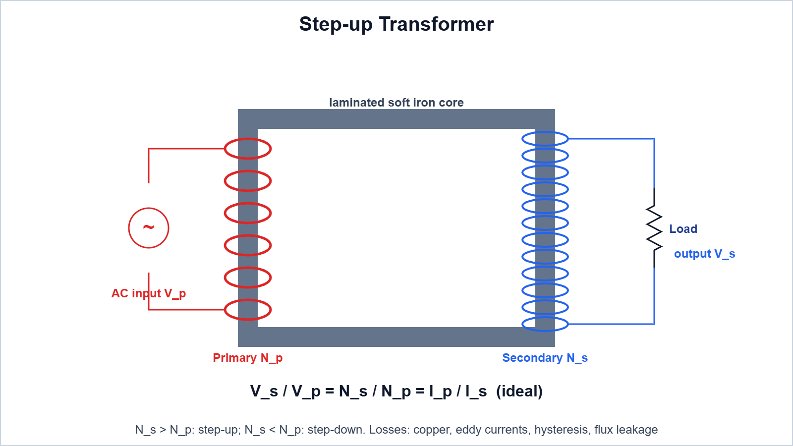
A transformer changes an alternating voltage using mutual induction. Two coils (primary Np, secondary Ns) are wound on a laminated soft-iron core. The same flux links each turn, so εs/εp = Ns/Np.
For an ideal transformer (no losses, input power = output power): Vs/Vp = Ns/Np = Ip/Is. Step-up: Ns > Np; step-down: Ns < Np.
Energy loss | Cause | Remedy |
|---|---|---|
Flux leakage | Not all flux of primary links the secondary | Wind coils one over the other |
Copper (Joule) loss | Resistance of windings | Use thick copper wire |
Eddy current loss | Currents induced in the core | Laminated core |
Hysteresis loss | Repeated magnetisation of the core | Soft iron core with a narrow loop |
Numerical 7: An ideal transformer has 100 primary and 2000 secondary turns. The primary is connected to 220 V AC. Find the secondary voltage, and the primary current when the secondary current is 0.5 A.
Given: Np = 100, Ns = 2000, Vp = 220 V, Is = 0.5 A
Formula: Vs/Vp = Ns/Np = Ip/Is
Solution: Vs = 220 × 2000/100; Ip = 0.5 × 2000/100
Answer: Vs = 4400 V; Ip = 10 A
Easy Memory Trick: “ELI the ICE man”: in an inductor (L) voltage E leads current I; in a capacitor (C) current I leads voltage E.
7. Practice Numericals (Answers Only)
- Find the rms value of an AC of peak 10 A. Ans: 7.07 A.
- Find the reactance of a 0.1 H inductor at 100 Hz. Ans: 62.8 Ω.
- Find the resonant frequency of L = 1 mH and C = 1 μF. Ans: about 5.03 kHz.
- What is the power factor of a pure inductor? Ans: Zero.
- A transformer steps 2200 V down to 220 V and has 500 primary turns. Find the secondary turns. Ans: 50.
8. Board-pattern Practice Questions
(a) Multiple Choice Questions
1. In a pure capacitor, the current
(A) lags voltage by 90° (B) leads voltage by 90° (C) is in phase with voltage (D) lags by 180°
Ans. (B)
2. At resonance in a series LCR circuit the impedance is
(A) maximum (B) zero (C) equal to R (D) equal to XL
Ans. (C)
3. The power factor of an LCR circuit at resonance is
(A) 0 (B) 0.5 (C) 1 (D) 0.707
Ans. (C)
4. Transformer cores are laminated to reduce
(A) copper loss (B) eddy current loss (C) flux leakage (D) hysteresis loss
Ans. (B)
(b) Assertion-Reason
Options: (A) Both A and R are true and R is the correct explanation of A. (B) Both A and R are true but R is not the correct explanation of A. (C) A is true but R is false. (D) A is false but R is true.
1. Assertion (A): A capacitor blocks DC but allows AC.
Reason (R): XC = 1/ωC is infinite for DC (ω = 0).
Ans. (A)
2. Assertion (A): The average power in a pure inductor is zero.
Reason (R): Current and voltage in an inductor are in phase.
Ans. (C) (They differ in phase by 90°.)
(c) Match the Columns
Column I | Column II |
|---|---|
(i) XL | (p) 1/√(LC) |
(ii) XC | (q) R/Z |
(iii) ω0 | (r) ωL |
(iv) Power factor | (s) 1/ωC |
Ans. (i)-(r), (ii)-(s), (iii)-(p), (iv)-(q)
(d) Case Study
Case: A radio receiver contains a series LCR circuit with a variable capacitor. Turning the tuning knob changes C. The station whose frequency equals the resonant frequency of the circuit produces the largest current and is heard clearly.
(i) Write the condition for resonance.
Ans. XL = XC, i.e. ω = 1/√(LC).
(ii) To tune to a higher-frequency station, should C be increased or decreased?
Ans. Decreased, since f0 ∝ 1/√C.
(iii) Why should R be small?
Ans. A small R gives a high Q, i.e. a sharp resonance, so nearby stations are rejected.
(iv) What is the phase difference between V and I at resonance?
Ans. Zero.
(e) Long Answer Questions
Q1. Using a phasor diagram, derive the impedance of a series LCR circuit. Find the condition for resonance and define the quality factor.
Ans. See Sections 3 and 4: Z = √[R2 + (XL − XC)2]; resonance at ω0 = 1/√(LC); Q = ω0L/R.
Q2. Derive the expression for average power in an AC circuit. What is wattless current?
Ans. P = VrmsIrms cos φ (Section 5). When φ = 90° the current does no work, so it is called wattless current (e.g. in a pure L or C).
9. Important Questions
Q1. Define rms value of alternating current.
Ans. The steady current that produces the same heat in a resistor in the same time; Irms = Im/√2.
Q2. How does XL vary with frequency?
Ans. It increases linearly (XL = ωL).
Q3. How does XC vary with frequency?
Ans. It decreases (XC = 1/ωC).
Q4. Define impedance.
Ans. The total opposition to AC in a circuit: Z = Vm/Im.
Q5. What is the resonant frequency of an LCR circuit?
Ans. f0 = 1/(2π√(LC)).
Q6. What is the power factor of a pure resistor?
Ans. 1.
Q7. Can a transformer step up DC voltage?
Ans. No; it needs a changing flux.
Q8. Why is a transformer core made of soft iron?
Ans. High permeability and low hysteresis loss.
Q9. What is the phase relation between VL and VC in series LCR?
Ans. They are 180° out of phase.
Q10. What does a high Q-factor mean?
Ans. A sharp resonance (good selectivity).
Conclusion: Alternating currents are described by rms values, reactances and phase. The series LCR circuit shows impedance, resonance and power factor, and the transformer uses mutual induction to change AC voltages for efficient transmission.